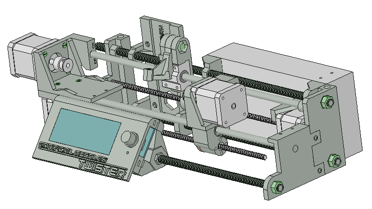
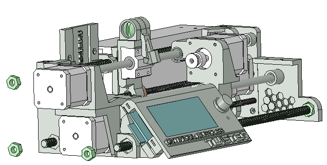
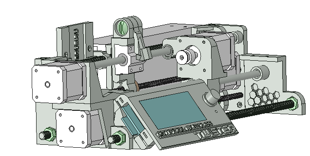
ARTIFICIAL MUSCLE TWISTER
Designed by Aleksandr Semochkin | Released under CC BY-SA 4.0
Assembly
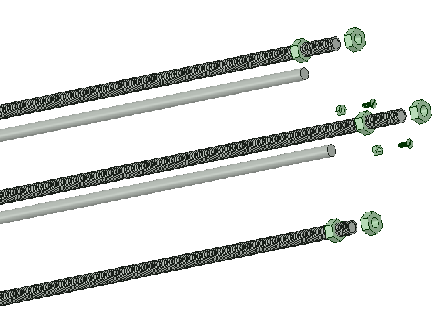
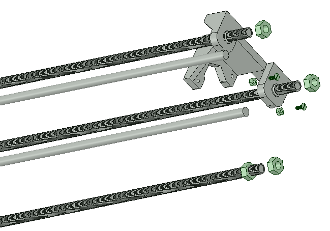
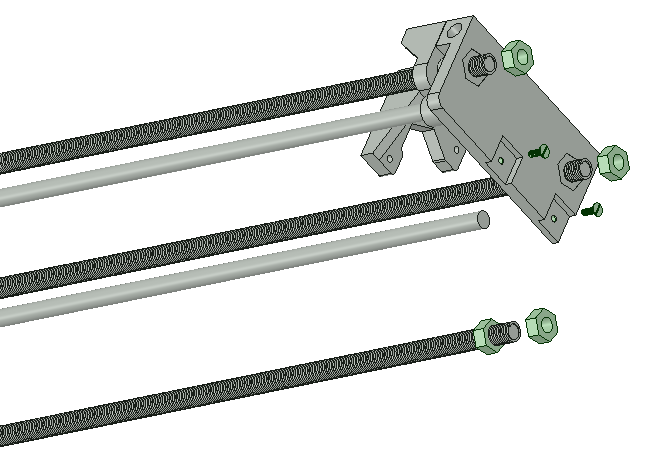
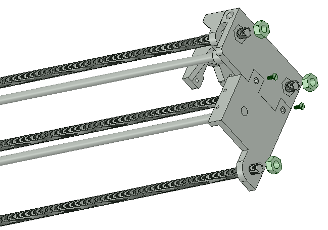
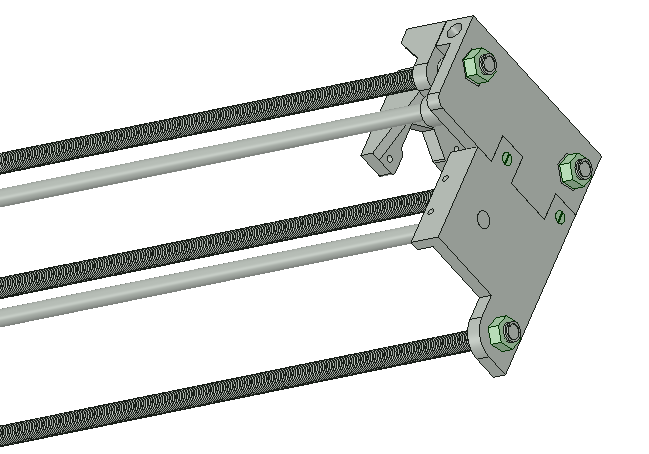
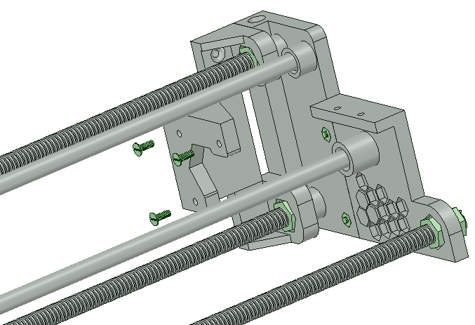
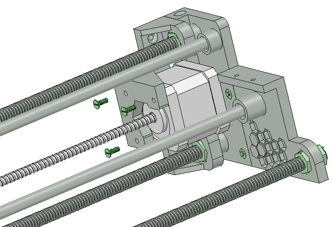
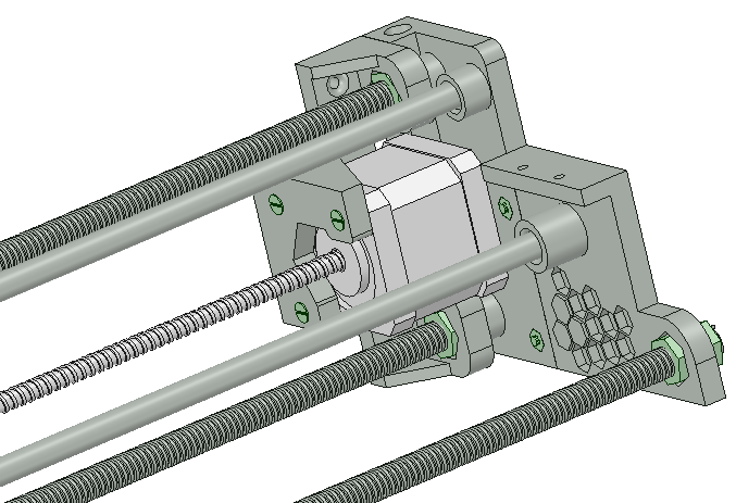
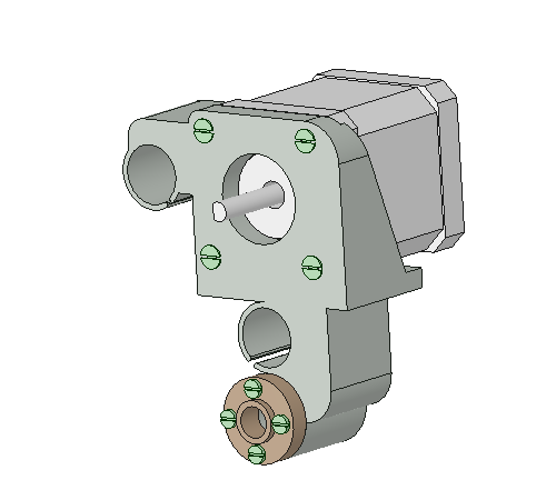
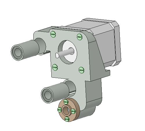
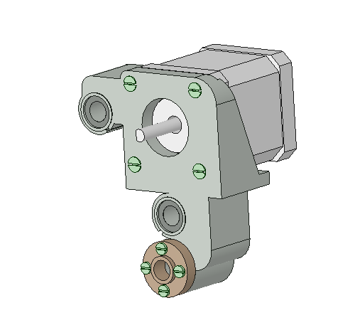
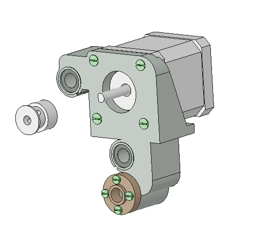
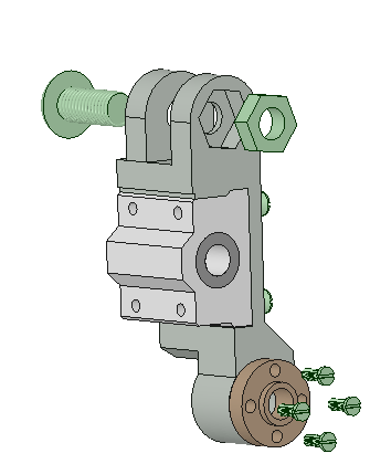
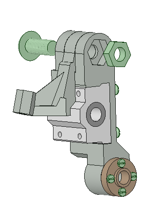
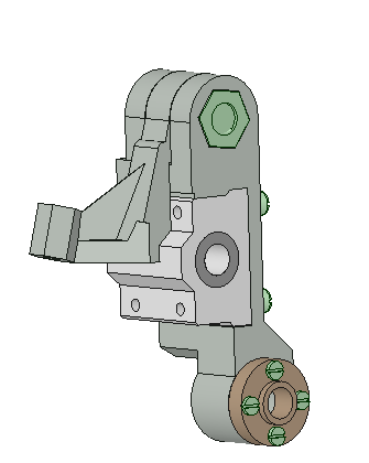
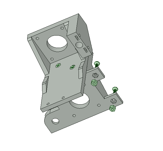
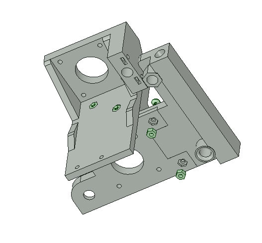
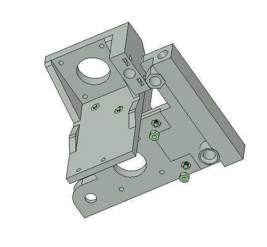
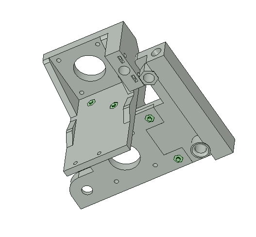
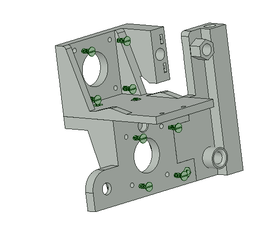
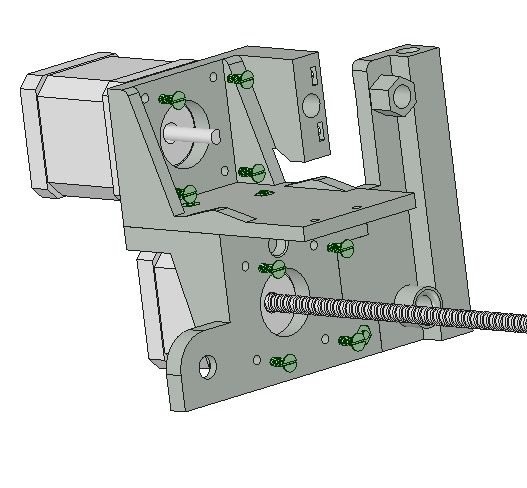
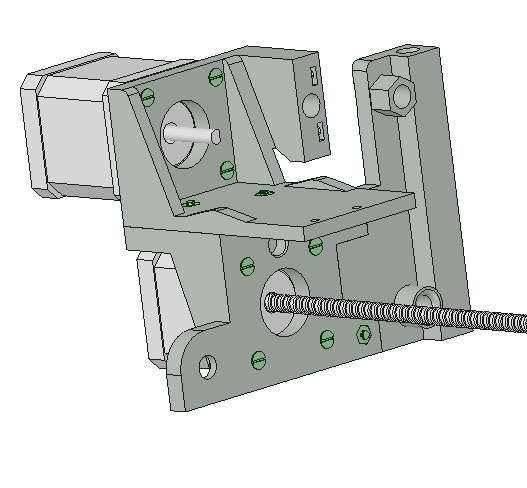
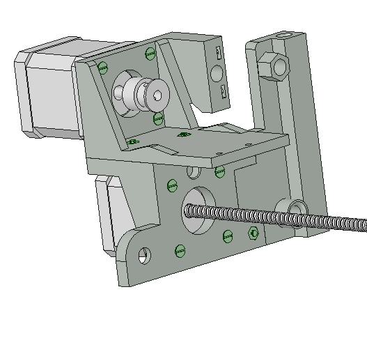
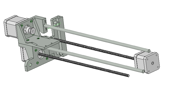
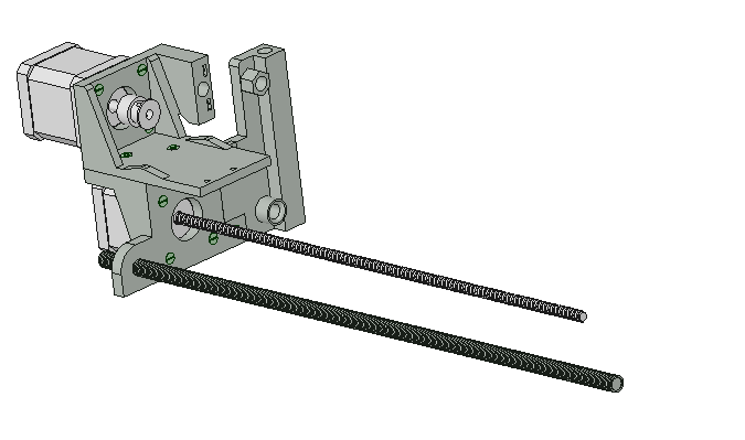
STAGE 1.The process of assembling the right side of the device.
Required components: 3 pcs of Fully Threaded Stud M8 x 38mm,
2 pcs of Standard Chrom Linear Optical Axis 8mm x 35mm,
6 pcs of M8 Nuts, 5 pcs of 3M bolts and 3 pcs of 3M nuts.
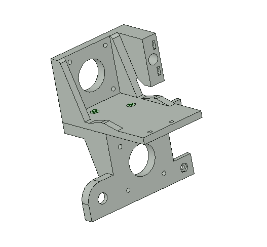
3D prints: SM4-Holder, R.Part-1, R.Part-2,
L.Part-1.
Electronics: A NEMA 17 screw linear stepper
motor T8 * 8 42 * 39 300 mm with cable (for 3D printing).
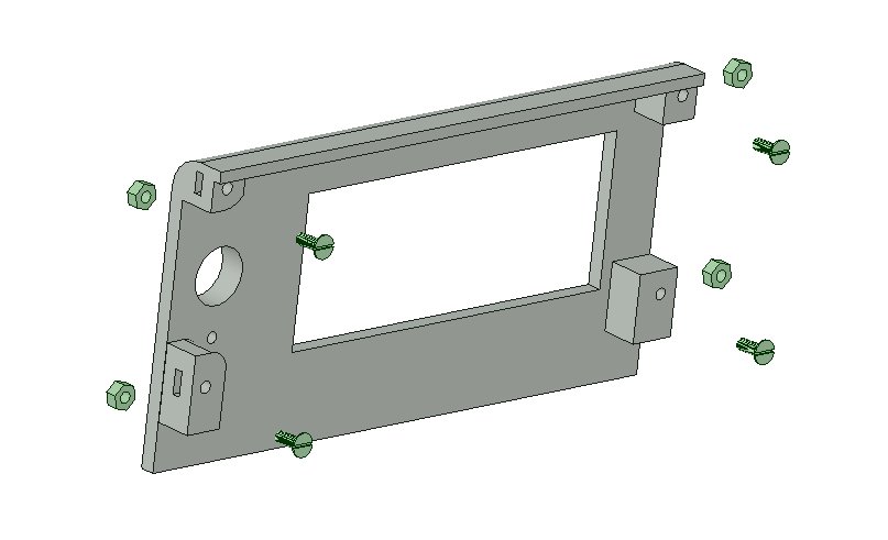
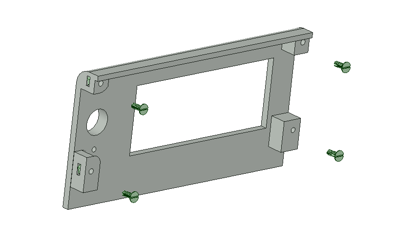
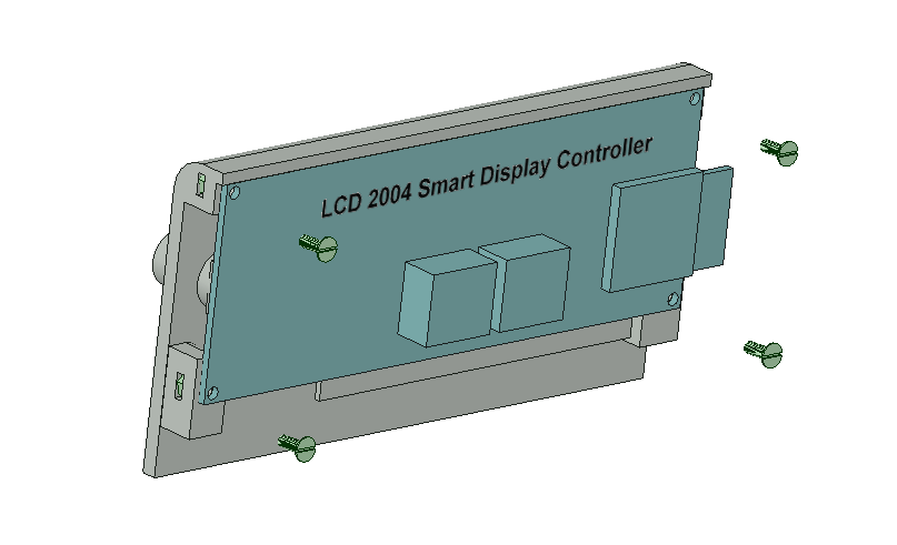
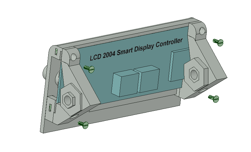
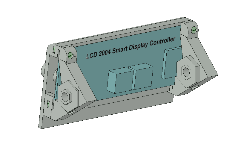
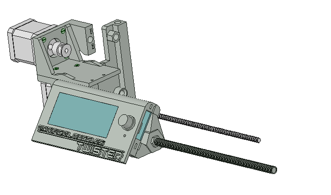
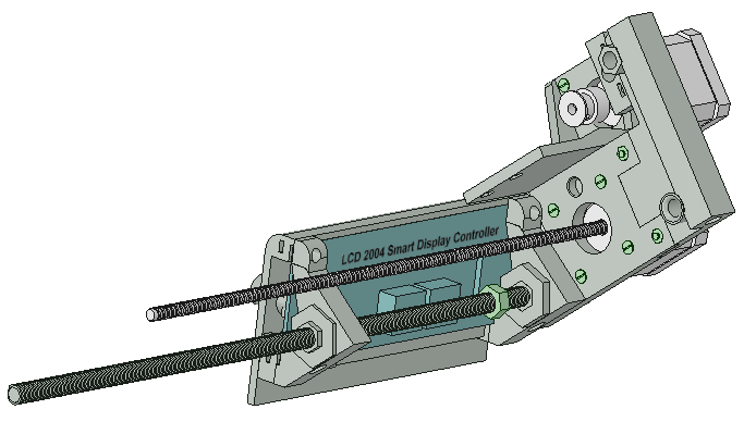
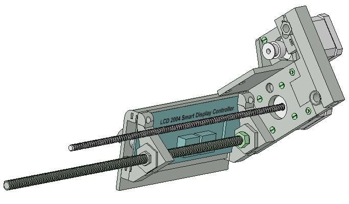
STAGE 2.The process of assembling the control panel.
Required components: 4 pcs of 3M bolts and 4 pcs of 3M nuts.
3D prints: LCDFace, LCDMount-1, LCDMount-2.
Electronics: LCD 2004 Smart Display Controller for RAMPS 1.4.
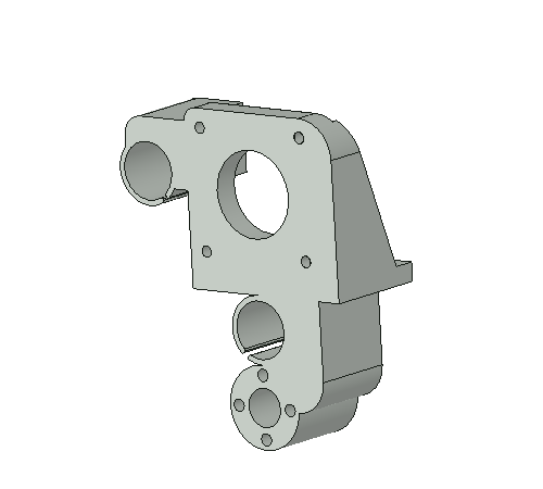
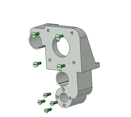
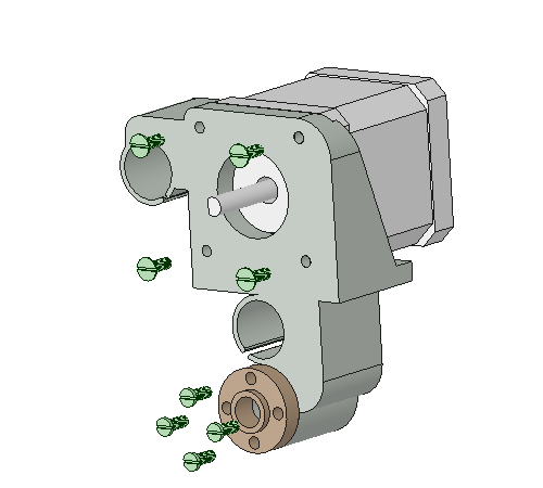
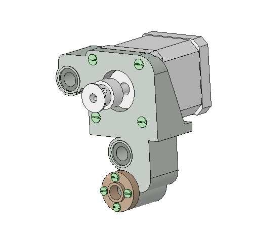
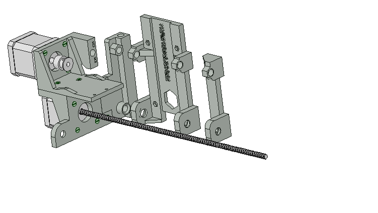
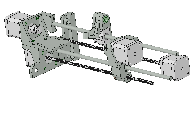
STAGE 3.The assemble guide of the mobile motor holder.
Required components: 8 pcs of 3M bolts,
2 pcs of the 8MM LM8UU linear motion ball bearing,
the carriage(traveling) nut, 5mm Aluminum Timing Pulley.
3D prints: SM2-Holder.
Electronics: A NEMA 17 stepper motor with a 1.7 x 1.7 inch (43.2 x 43.2 mm) faceplate.
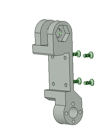
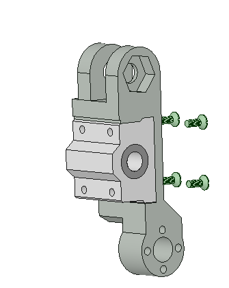
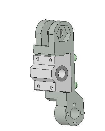
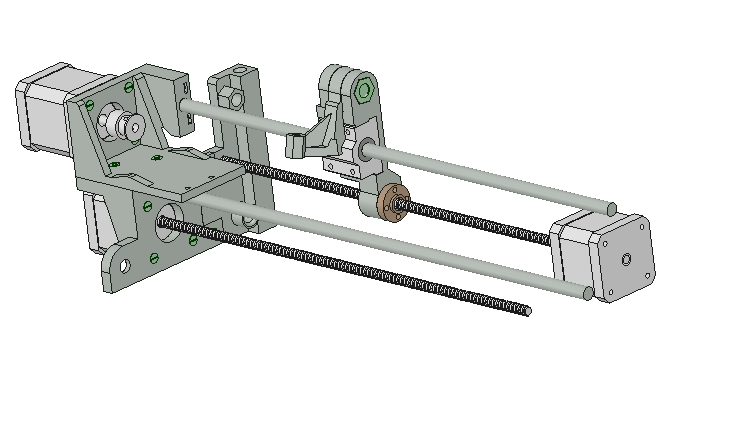
STAGE 4.The assemble process of the wire guide slider.
Required components: 8 pcs of 3M bolts,
1 pcs of the Socket Button Screws A2 Stainless Steel M8 x 20mm,
1 pcs of the 8M Nut, the carriage(traveling) Nut,
SC8UU 8mm Aluminum Linear Motion Ball Bearing Slide Bushing.
3D prints: Slider, Nozzle.
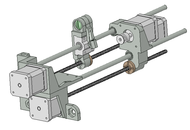
STAGE 5.The assemble process of the left side.
Required components: 12 pcs of 3M bolts,
4 pcs of 3M nuts, 5mm Aluminum Timing Pulley.
3D prints: SM1-Holder, SM1-Holder, L.Part-1.
Electronics:
A NEMA 17 stepper motor with a 1.7 x 1.7 inch (43.2 x 43.2 mm) faceplate,
A NEMA 17 screw linear stepper motor T8 * 8 42 * 39 300 mm with cable (for 3D printing).
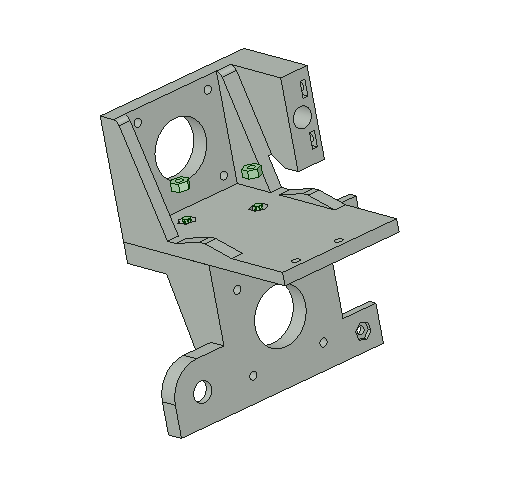
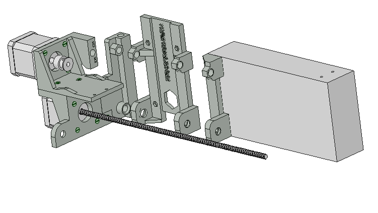
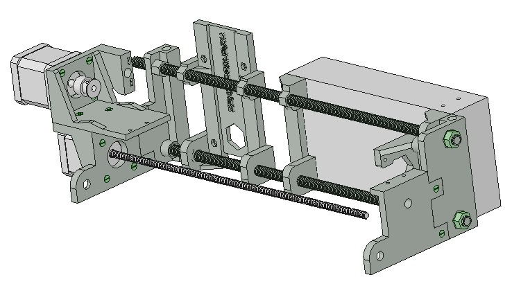
STAGE 6.The assemble process of the base.
Required components:
the right side, the left side of the device,
the wire guide slider, the mobile motor holder, the control panel,
4 pcs of M8 Nuts
3D prints: M.Part-1, RAMPS-Holder.
Electronics:Power supply model S-250W-12V.
